
This module introduces robotics controllers, with a specific focus on the VMX-pi and its role in real-time robotic systems. You will learn how a controller acts as the central unit of a robot, managing communication between sensors, actuators, and processing systems. It explains the limitations of general-purpose computers such as the Raspberry Pi, why a dedicated real-time controller is required, and the key features of the VMX-pi — power management, communication interfaces, and input/output systems. It also introduces the hardware layout and pin configurations you need to connect components correctly and safely. This module forms the foundation for all hardware interaction in robotics.
- What is the main role of a controller in a robotic system?
- Why is a real-time controller needed instead of just using a Raspberry Pi?
- What types of components connect to a robotics controller?
- Why is it important to understand pin layouts when working with hardware?
2.1 Introduction to Robotics Controllers
A robotics controller is the central unit responsible for managing all operations within a robot. It acts as the bridge between hardware and software, ensuring that inputs from sensors are processed correctly and that outputs to actuators are executed accurately. In simple terms, the controller is the brain of the robot, coordinating all activities so the robot behaves as intended.
Without a controller, a robot cannot:
- Process sensor data
- Make decisions
- Control movement
2.2 What is the VMX-pi?
The VMX-pi is a high-performance robotics controller designed to work alongside a Raspberry Pi. It provides the real-time control capabilities required for robotics applications while leveraging the processing power of the Raspberry Pi. Unlike standard microcontrollers, the VMX-pi is specifically built for robotics, offering:
- Real-time processing
- Reliable motor control
- Integrated sensor support
- Stable communication interfaces
2.3 Why Not Use a Raspberry Pi Alone?
A Raspberry Pi is a powerful computing device, but it is not designed for real-time control. The two work best together — the Pi handles high-level computing while the VMX-pi handles precise, time-critical control.
| Raspberry Pi | VMX-pi |
|---|---|
| High-level processing | Real-time control |
| Not time-critical | Time-critical |
| General computing | Robotics-focused |
2.4 Core Features of the VMX-pi
1. Power Management
- Protects components from voltage fluctuations
- Ensures stable system operation
2. Integrated IMU
Measures acceleration, rotation, and heading. Used for:
- Navigation
- Balancing
- Orientation tracking
3. Communication Interfaces
- I2C
- SPI
- UART
- Digital & Analog I/O
4. Digital and Analog I/O
Used for buttons, LEDs, sensors, and control signals.
2.5 VMX-pi Hardware Layout
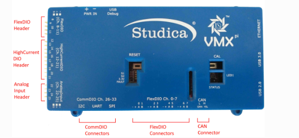
2.6 Connector Types
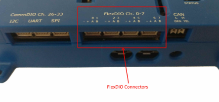
Three types of connectors are used on the VMX-pi:
- 3-pin PWM-style connector
- 4-pin JST GH connector
- 2-wire CAN connector
2.7 FlexDIO
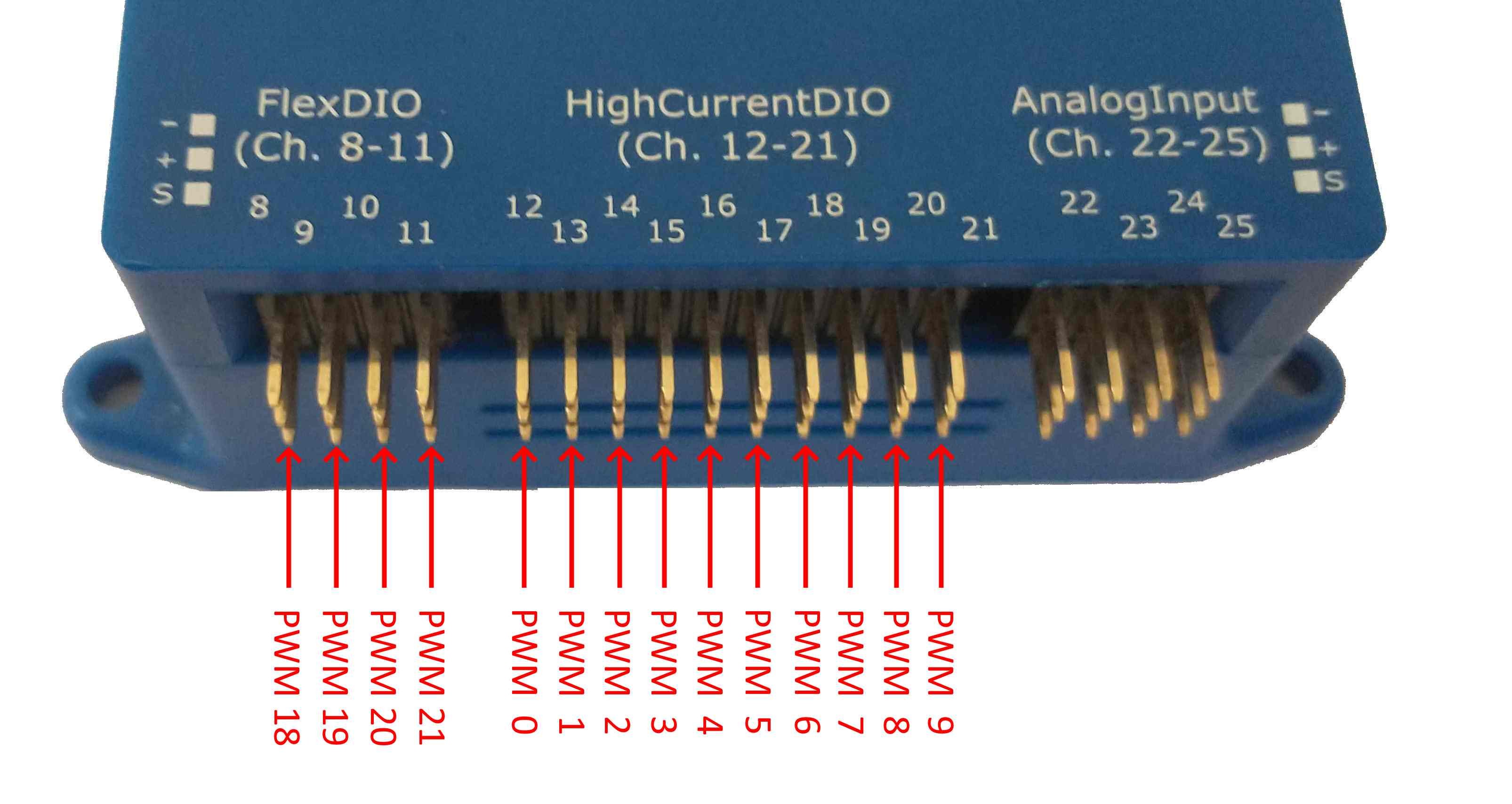
FlexDIO is used for encoders, PWM signals, and digital I/O. The diagram below shows the FlexDIO header and its WPILib PWM channel addressing.
2.8 High-Current DIO
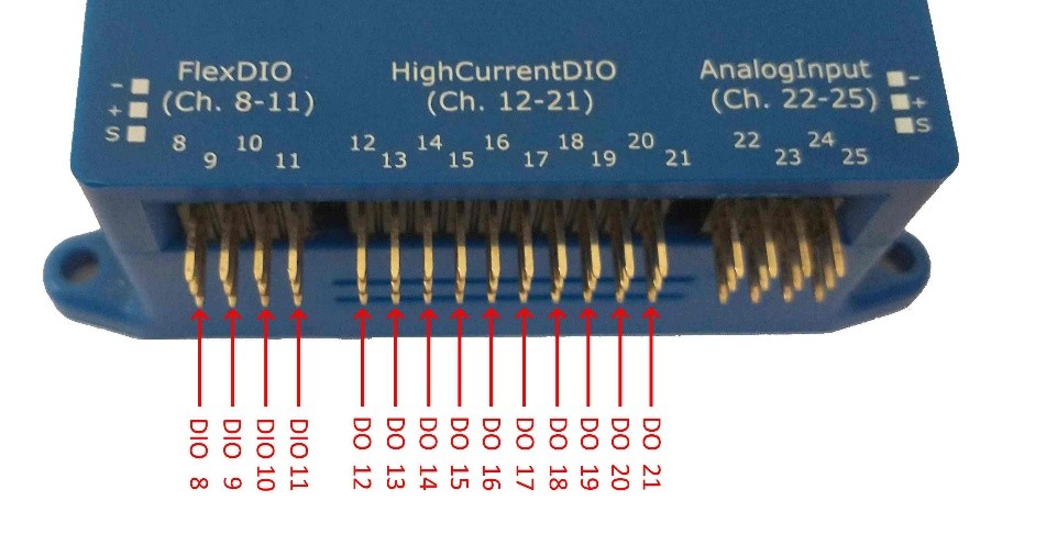
Used for relays, motors, and other high-power outputs. The diagram below shows the header and its WPILib DIO channel addressing.
2.9 Analog Inputs
Used for potentiometers, distance sensors, and other analog signals.
2.10 Communication Ports (CommDIO)
Supports I2C, UART, and SPI.
2.11 Digital Communication Ports
The WPILib SerialPort class uses these identifiers:
kOnboard→ RS-232 (not available on VMX)kMXP→ TTL UART (VMX CommDIO "UART" port)kUSB,kUSB1,kUSB2→ USB Serial via Raspberry Pi USB ports
| Identifier | Type | Notes |
|---|---|---|
kOnboard | RS-232 Port | Not implemented on VMX |
kMXP | TTL UART | VMX CommDIO "UART" connector |
kUSB | USB Serial Port | Raspberry Pi "top-left" USB port (aka kUSB1) |
kUSB1 | USB Serial Port | Raspberry Pi "top-left" USB port |
kUSB2 | USB Serial Port | Raspberry Pi "bottom-left" USB port |
kUSBandkUSB1refer to the same USB port and can't be used at the same time.- TTL UART: up to 230400 bps.
- USB Serial: much faster, depending on the USB and device capabilities.
The Raspberry Pi 4 provides multiple USB ports that support the USB Serial standard; the WPILib serial-port identifiers are mapped to those USB ports as shown in the layout diagram (section 2.5).
2.12 I2C Port
The VMX includes one I2C port, addressable via kOnboard or kMXP. I2C speeds:
- Default: 100 kHz (Standard Mode)
- Can be set to 400 kHz (Fast Mode) on Raspberry Pi
2.13 Important: Pin Layout Usage
You MUST use the pinout diagrams above when:
- Wiring sensors
- Connecting encoders
- Setting up communication devices
Incorrect wiring can cause damage to components, incorrect readings, or system failure.
2.14 Real-Time Control in Robotics
Real-time control ensures immediate response to inputs, accurate motor control, and stable system behaviour.
2.15 How the Controller Connects to the Robot
The system flow is: Sensors → Controller → Actuators. This is the foundation of all robotics systems.
2.16 Importance of Proper Setup
Proper setup ensures stable communication, accurate readings, and reliable performance.
2.17 Industrial Relevance
Controllers like the VMX-pi are used in automation systems, industrial robotics, and real-world engineering.
Key Terms
| Term | Meaning |
|---|---|
| Controller | The central unit that processes sensor input and drives actuator output — the "brain" of the robot. |
| VMX-pi | A robotics controller that adds real-time control to a Raspberry Pi. |
| IMU | Inertial Measurement Unit — measures acceleration, rotation, and heading. |
| FlexDIO | Flexible digital I/O header used for encoders, PWM, and digital signals. |
| CommDIO | Communication + digital I/O ports supporting I2C, UART, and SPI. |
| Real-time control | Control that responds to inputs immediately and predictably, as required for reliable robotics. |
- Explain the difference between a Raspberry Pi and a VMX-pi.
- List three key features of the VMX-pi.
- Explain how sensors, controllers, and actuators work together.
- Use the pin layout diagrams above to correctly wire a device.